

Introduction
Layer 3 Catalyst switches incorporate routing functionality which allows the switch to perform interVLAN routing. This document provides the configuration and troubleshooting steps applicable to this capability.
Configuring InterVLAN Routing
Task
In this section, you are presented with the information to configure the features described in this document. The following logical diagram explains a simple interVLAN routing scenario. The scenario can be expanded to include a multi−switch environment by first configuring and testing inter−switch connectivity across the network before configuring the routing capability.

Step−by−Step Instructions
Do the following to configure a switch to perform interVLAN routing.
1). Enable routing on the switch using the ip routing command. Even if IP routing was previously enabled, this step ensures that it is indeed activated.
Switch(config)#ip routing
Note: If the switch does not accept the ip routing command, you will need to upgrade to either SMI image 12.1(11)EA1 or later, or an EMI image, and repeat this step. Refer to the Prerequisites section for more information.
Tip: Check the show running−configuration and verify whether ip routing is enabled. The command, if enabled, will appear towards the top of the output.
hostname Switch
!
!
ip subnet−zero
ip routing
!
vtp domain Cisco
vtp mode transparent
2). Make note of the VLANs that you want to route between. In our example, we want to route traffic between VLANs 2, 3 and 10.
3). Use the show vlan command to verify that the VLANs exist in the VLAN database. If they do not exist, you must add them on the switch.
Switch#vlan database
Switch(vlan)#vlan 2
VLAN 2 added:
Name: VLAN0002
Switch(vlan)#vlan 3
VLAN 3 added:
Name: VLAN0003
Switch(vlan)#vlan 10
VLAN 10 added:
Name: VLAN0010
Switch(vlan)#exit
APPLY completed.
Exiting....
Tip: You can use VTP to propagate these VLANs to other switches. Refer to the document Understanding and Configuring VLAN Trunk Protocol (VTP).
4). Determine the IP addresses you want to assign to the VLAN interface on the switch. For the switch to be able to route between the VLANs, the VLAN interfaces must be configured with an IP address. When the switch receives a packet destined for another subnet/VLAN, the switch looks at the routing table to determine where to forward the packet. The packet is then passed to the VLAN interface of the destination and in turn it is sent to the port where the end device is attached.
5). Configure the VLAN interfaces with the IP address identified in Step 4.
Switch#conf t
Enter configuration commands, one per line. End with CNTL/Z.
Switch(config)#interface Vlan2
Switch(config−if)#ip address 10.1.2.1 255.255.255.0
Switch(config−if)#no shutdown
Repeat this process for all VLANs identified in Step 1.
6). Configure the interface to the default router. In this scenario we have a Layer 3 FastEthernet port.
Switch(config)#interface FastEthernet 0/1
Switch(config−if)#no switchport
Switch(config−if)#ip address 200.1.1.1 255.255.255.0
Switch(config−if)#no shutdown
The no switchport command makes the interface Layer 3 capable. Also notice that the IP address is in the same subnet as the default router.
Note: This step can be omitted if the switch can reach the default router through a VLAN. In its place, configure an IP address for that VLAN interface.
7). Configure the default route for the switch
Switch(config)#ip route 0.0.0.0 0.0.0.0 200.1.1.2
From the diagram in the Task section, note that the IP address of the default router is 200.1.1.2. If the switch receives a packet for a network not in the routing table, it forwards it to the default gateway for further processing From the switch verify that you can ping the default router.
Note: The ip default−gateway command is used to specify the default gateway when routing is not enabled. However, in this case, routing is enabled (from Step 1) hence the ip default−gateway command is unnecessary.
8). Configure your end devices to use the respective Catalyst 3550 VLAN interface as their default gateway For example, devices in VLAN 2 should use the interface VLAN 2 IP address as its default gateway. Refer to the appropriate client configuration guide for more information on designating the default gateway.
Verify
This section provides information you can use to confirm your configuration is working properly. Certain show commands are supported by the Output Interpreter Tool ( registered customers only) , which allows you to view an analysis of show command output.
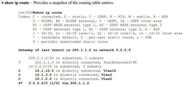
Note that the routing table has an entry for each VLAN interface subnet. Hence, devices in VLAN 3 can communicate with devices in VLAN 10, VLAN 2 and vice versa. Also, the default route with the next hop 200.1.1.2 allows the switch to forward traffic to the gateway of last resort (for traffic the switch cannot route).
•Switch#show ip interface brief − Lists a brief summary of an interface's IP information and status. This command can be used to verify that the VLAN interfaces and ports on the switch are up/up.
Post a Comment